Home / News & Events / Industria News / Sub-10ms STS Switching Explicata: MS-MPPT400-2 vs MS-TS500-2
-
 GRAVITER Shipping
-
 AEMULUS PRETIUM
-
 PRAESTANS POST SERVITIUM

Ut sine Quote
 0
0


Industria News
Jul 14,2026
Sub-10ms STS Switching Explicata: MS-MPPT400-2 vs MS-TS500-2
Decem Milliseconds quod volueris utrum a Site Stays nectunt
Defectum eget non ipsum nuntiat. Uno momento sedem trahit ab utilitate; Proxima, intentione ruit et omne amni onus obicitur hiatum quem ferre non potest. Ad centrum datae, cellarium frigidum, vel productio linea media cycli, quae hiatus occludere debet in singulis digiti milli secundis, non secundis, non "quantum generans nere potest". Hoc problema proprium machinalis STS (translatio mutandi stabilis) stratum solvit, et cur suggestum Deye MC-L430 aedificat, commutationes circa duo repositoria constructa: MS-MPPT400-2 et MS-TS500-2, utrumque pro translatione sub-10ms aestimavit.
Hae duae repositoriae similes in schedula - manubrio craticulae, generantis, et confractores onerant; uterque unum digitum millisecondum commutatione affirmant — sed problemata diversa solvunt. PV input cum commutatione in una clausura coniungit. Alterum dedicatum est, altioris capacitatis mutandi scrinium cum nullo PV functione. Distinctio ista ius questus est quod determinat an architecturae mutandi situs generationi suae misceat actu.
Quid est Static serie SWITCH PB
Translatio static transitum mechanice contactum non movet ut via traditio automatic translatio transitum facit. Commutatione solida utitur ut fontem defectum deprehendat et onus in alternum fontem revolvat antequam onus semper interruptionem videat. Hoc mechanism post suggestum's ≤10ms mutandi tempus inter operationem in-grid et extemporalitatem — satis hercle ut onera electronic sensitiva numquam transitus omnino subcriptio.
Ambae MS-MPPT400-2 et MS-TS500-2 circa eandem mutandi nucleum aedificantur, sed utraque arca praevaricatores circa eam disponit aliter secundum quod aliud clausura communicare debet.
MS-MPPT400-2: Switching and Solar Input in One Cabinet
MS-MPPT400-2 duo munera coniungit quae ferramentis separatis aliter egent: dual-alvei MPPT scaena tractans usque ad 400kW de PV input (2 x 200kW), et scaena STS ad 400kW per onus, craticula et nexus machinalis olei aestimatus est. In PV parte decurrit a max inputatione 800V DC, MPPT amplitudo intentionis 180-750V DC, et 200V inceptio — satis late ad aptandum chordarum figurarum sine PV separato inverso.
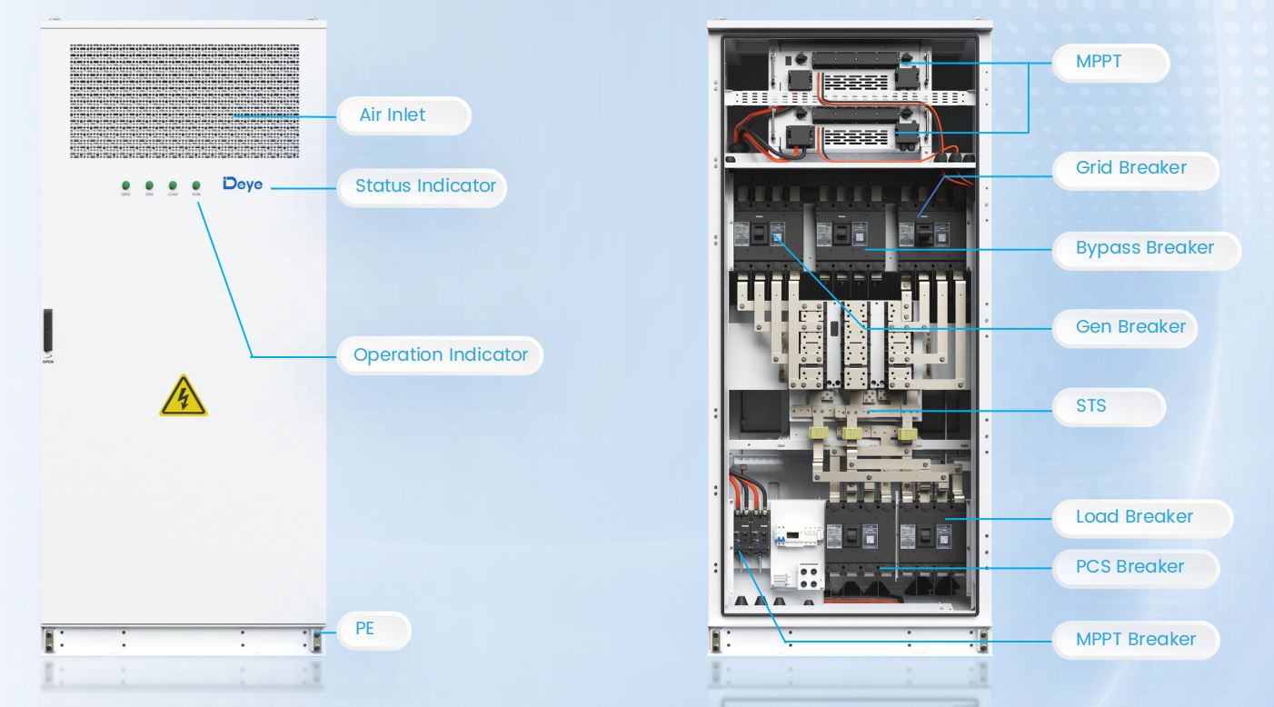
Praevaricator layout in medio scrinii ostendit munus illud duale: dedicatum MPPT ruptor et eget ruptor sedent iuxta bypass ruptor, generator ruptor, onere ruptor, et PCS ruptor - omnia a logica interna STS ordinatae. Multum mutandi intellegentiae in unam clausuram 1000 x 1000 x 2450mm refertam est, et plane est cur haec scrinium in propositionibus DC-coniunctis ostendit ubi PV, altilium, et mutandi necessitatem unum punctum AC connexionis potius quam tres arcae separatas communicare.
MS-TS500-2: Dedicata Switching scrinium pro Larger Loads
MS-TS500-2 munus PV totum demittit et in unum officium tendit: commutatio inter eget, generans et onera in altiori aestimatione quam arca MPPT integratae offerre potest. Pro 500kW trans onus, grid, et oleum machinarum nexus aestimavit — 100kW plus capitis quam MS-MPPT400-2 — cum busbaralibus apud 1000A et ramum in 200A busbaribus aestimatum, currentem in rating insulatione 1000V DC.
| Parameter | MS-MPPT400-2 | MS-TS500-2 |
|---|---|---|
| PV input function | Ita, 400kW (2x200kW MPPT) | No |
| Rated switching potentia (onus/eget/olei engine) | 400kW uterque | 500kW quisque |
| Switching tempore | ≤10ms | ≤10ms |
| Busbar rated current | N/A (consilium integratum) | 1000A |
| Nulla voltage | N/A | DC1000V |
| Dimensiones (W x D x H) | 1000 x 1000 x 2450mm | 1000 x 1000 x 2365mm |
| Pondus | ≤950kg | ≤700kg |
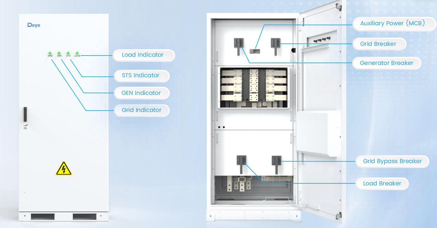
Practica legitur: cum situs iam PV per scrinium separatum DC-coniunctum MPPT tractavit, vel nihil PV habet - puram machinationem plus-generatoris tergum instruere, exempli gratia - MS-TS500-2 facultatem mutandi plus dat sine solutione pro scaena PV quae insolita eat.
Eligentes Inter eas Ex Site Mathematicae
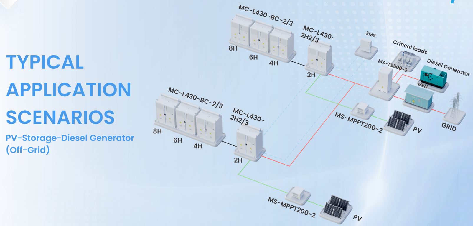
Consilium generaliter descendit ad quot functiones unius scrinii opus est ad hauriendum, et quantum facultatem mutandi onus actu requirit. Tergum potentia instruere instruere onera critica cum arcae N≤2 configurationis typice paria repositorum altilium cum MS-TS500-2 sedentem inter ripam pugnae EMS ordinatae et transformantis — nulla PV in illa catella particulari, nulla ergo ratio est ferramenta MPPT portandi.
Repono microgrid generans PV, contra, iter per MS-MPPT400-II tendit, cum PV input scaenam usquam indigeat et STS integratum minus arcae ad institutionem, filum et commissionem significat. In instruere pellentesque subnixum, idem MS-MPPT400-II tractat omnes tres vias translationis - eget, generans et altilium PV saturatum ex una clausura, servans pacti topologiam mutandi sicut generatio mix plus implicat.
Neutra scrinium separatim a lavacro EMS operatur. Utriusque status renuntiationis et significationum potestate accepta super idem RS485/Modbus TCP/DIDO narum reliquos suggesti usus, quod est quod sinit EMS coordinare decisionem transferendi cum statu oneris et onere prioritatis potius quam commutatione pure in limine voltage.
Quid Sub-10ms magis quam sonat
Decem milliseconds circiter dimidium cycli est 50Hz. Limen illud non est arbitrarium - positum est manere sub equitatione per tolerantiam instrumenti maxime verisimile laedi aut rumpi interruptione: variabilis frequentia agit, UPS backed IT onera, et praecisio fabricandi moderatoris qui omnem intentionem stillicidium tanquam culpam conditionem tractant et in defensione claudit. Virgula quae 100ms capit, vel etiam 50ms, adhuc scandali clausulae defensivae potest, etsi potentia technica numquam plene evanescit.
Hac de causa etiam munus mutandi ut categoriae ferrariae propriae tractatur potius quam in PCS vel scrinium pilae complicatum. Relinquendo eam in armario dedicato STS expedito — sive MS-MPPT400-II sive MS-TS500-2 - hoc significat decisionem mutandi non expectare in logica vel PCS synchronisationi pugnae, quod est ubi numerus sub- 10ms actu ex usu venit.
Ut architecturae canalis profundioris naufragii et specificationum commutationes post hanc generationem ferramenti, scriptor suggestus VIII, alveo MPPT et 500kW STS specificationem naufragii mutandi hardware fusius tegit. Pro iugis aestimandis quomodo haec permutatio iacuit in plenam instruere aciem, latioribus C&I ESS solution lineup initium est pro adaptare scrinium comiti, modus copulandi, et mutandi facultatem ad certum locum obtinendi.
←
Deye GE-F128/F240/F256 Series Outdoor Battery Cabinet: Small-Scale C&I ESS Guide
→
Supra repono: quomodo MS-EMS vertit Arbitragium et demanda Responsio in Revenue
related products



Solutions
Contactus info.
 +31610999937
 [email protected]
 De Werf 11, 2544 EH Hagae, Nederland.
QR code
Copyright © 2023 Uni Z Sacra B.V. VAT: NL864303440B01 All Rights Reserved
